SOLID-SEGMENT
SCULPTURES
George W. Hart
Abstract
Several sculptures and designs illustrate
an algorithmic technique for creating solid three-dimensional structures from
an arrangement of line segments in space. Given a set of line segments,
specified as a position in 3-dimensional space for each endpoint, a novel
algorithm creates a volume-enclosing solid model of the segments. In this solid
model, a prismatoid-like strut represents each segment. The method is very
efficient with polygons and produces attractive lucid models in which the sides
of the "prismatoids" are oriented in directions relevant to the
structure. The algorithm is applicable to a wide range of structures to be
realized by 3D printing techniques.
1. Sculpture by 3D Printing
As
an artist of constructive geometric sculpture, I often visualize forms and then
need to develop new techniques which enable me to create them. [5-10] This
paper describes a new method for creating geometric structures which correspond
to a given arrangement of line segments. The procedure is an essential
step in my design of several recent sculptures.
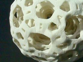
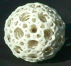 Figure 1 shows a 10 cm diameter sculpture titled Deep Structure,
consisting of five nested concentric orbs. Each of the five has the same
structure as the outer, most visible, orb: there are 30 large 12-sided oval
openings, 12 smaller 10-sided openings, 80 irregular hexagonal openings, and
120 small rectangular openings. Oval "corkscrew spirals" in the
12-sided openings connect the layers with each other. The concept is
based on familiar concentric ivory spheres which are traditionally turned on a
lathe and hand carved, with holes in each layer providing access to the inner
layers. However, Figure 1 is created in plaster by an automated 3D
printing process, without any human hand. After I design such a sculpture
as a computer file, it is fabricated in a machine which scinters, laminates, or
solidifies thousands of very thin layers. [2] This piece and the next were
printed by Zcorp [16].
Figure 1 shows a 10 cm diameter sculpture titled Deep Structure,
consisting of five nested concentric orbs. Each of the five has the same
structure as the outer, most visible, orb: there are 30 large 12-sided oval
openings, 12 smaller 10-sided openings, 80 irregular hexagonal openings, and
120 small rectangular openings. Oval "corkscrew spirals" in the
12-sided openings connect the layers with each other. The concept is
based on familiar concentric ivory spheres which are traditionally turned on a
lathe and hand carved, with holes in each layer providing access to the inner
layers. However, Figure 1 is created in plaster by an automated 3D
printing process, without any human hand. After I design such a sculpture
as a computer file, it is fabricated in a machine which scinters, laminates, or
solidifies thousands of very thin layers. [2] This piece and the next were
printed by Zcorp [16].
 Figure 1. Deep Structure, George W. Hart,
2000.
Figure 1. Deep Structure, George W. Hart,
2000.
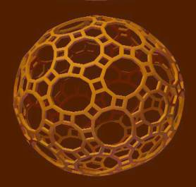
Figure 2 shows a second 3D
printing sculpture, about 8 cm in diameter. This is based on a projection
of the regular 4-dimensional polytope called the "120-cell," but
adapted into a more textured, chiseled form. There are many 5-sided
openings and passages throughout its volume. The title Five-Legged-Bee
Hive whimsically refers to the fact that bees with six legs make six-sided
hives. (Thank you to Sandor Fekete for the suggestion.) Both these sculptures
can be idealized as a set of line segments connecting points in
three-dimensional space. However, the lines here are not simple
cylindrical rods. I designed angular, faceted struts to give these works
more sculptural presence
Figure 2. Five-Legged-Bee Hive, George W. Hart, 2000.
2. Visual presentation of
segment structure
An
ideal mathematical line has zero thickness. For rendering lines on
two-dimensional computer displays, simple standard algorithms have been
developed which produce lines one pixel in thickness, to be as close as
possible to the mathematical ideal, yet clearly visible. For producing
lines in three-dimensional space, other techniques are necessary.
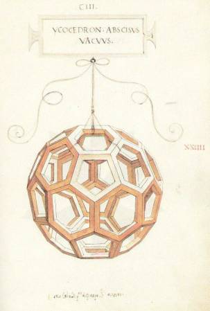
 Leonardo da Vinci invented a solid segment representation of
polyhedra for the illustrations to Luca Pacioli's 1509 book, De Divine
Proportione. Prior to this, polyhedra were illustrated as either opaque
solids or transparent line drawings. Opaque representations have the
disadvantage of hiding the rear structure. Simple line drawings can produce the
"Necker cube" illusion, in which it is not clear whether a line
belongs to the front or rear surface.
Leonardo da Vinci invented a solid segment representation of
polyhedra for the illustrations to Luca Pacioli's 1509 book, De Divine
Proportione. Prior to this, polyhedra were illustrated as either opaque
solids or transparent line drawings. Opaque representations have the
disadvantage of hiding the rear structure. Simple line drawings can produce the
"Necker cube" illusion, in which it is not clear whether a line
belongs to the front or rear surface.
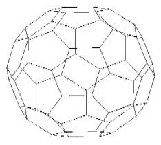
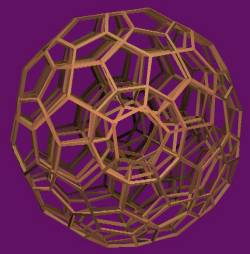
Figure 4. Line drawing of truncated icosahedron
displays "Necker cube"
ambiguity between front and rear surface. In Leonardo's new form of representation, thick
segments and open faces show the front and back structure, avoiding both
problems.
Many styles for
solid-segment models are possible. Consider, for example, molecular models used
by chemists, with cylindrical struts and spheres at each vertex. Leonardo used
consistent, implicit rules in his 3D designs such as Fig. 3: (1) outer faces of
struts are made in the planes of the polyhedron faces, (2) the inner faces are
parallel to the outer faces, and (3) the "side faces" are
perpendicular to the inner and outer faces. This makes for a very lucid
presentation of convex polyhedra, but it does not generalize to an arbitrary
network of vertices and segments, in which the structure need not determine
planes tangent to the surface of a sphere. In the design of geometric
sculpture, I faced the problem of connecting a set of points in space with
faceted struts of some form, and needing an algorithmic procedure to design
interesting struts.
3. Statement of problem
The
abstract problem considered here is that we are given a set of (x,y,z)
points in space, plus the information that various pairs of these points are to
be connected via line segments. It is not difficult to produce the necessary
vertex coordinates and edge lists for polyhedra [11-13] or polytope
projections [3]. However, to produce 3D printings, line segments
are not sufficient; one must have a set of polygons which enclose volume.
This is an open-ended problem that can be approached in many ways. One tradeoff
is between the number of polygons and how closely the result surrounds the
segments. There are also many approaches to choosing the struts' shapes, sizes,
and orientations. Selecting among these choices will depend on the
application. A different approach with different properties is described
in [1].
As background, consider two
approaches to this problem that were found unsuitable. The Union
operator of constructive solid geometry is a standard tool for combining 3D
objects into more complex objects. [2] It is straightforward to produce prisms,
antiprisms, or other approximations to cylinders for each segment and then call
a Union subroutine to combine them. However, this approach fails in
practice for large data sets, because of the instability of the union operator
when using floating point data, even in large, expensive, commercial software
packages. Plus, a serious drawback to this approach is that if it succeeds, it
results in a large number of polygons.
Another approach is to
create cylindrical approximations for each strut as above, but not to union
them as 3D objects. Instead the effect of the union operation may be
achieved on a voxel scale in the cross-sectioning software which creates the
layer data that control the 3D printing. Again, there is a likelihood
that the software will fail when given a complex structure with many
overlapping components. But more fundamentally, these structures will not
be visually lucid, because the orientation of the faces of the cylindrical
approximations are designed individually, so are not relevant to the overall
structure.
4. New approach
The
algorithm is presented in reverse here, starting with the final step.
Step 3. Make Struts. Given two polygons that surround the ends of a line segment, take their
convex hull to construct a "prismatoid" that surrounds the body of
the segment. A prismatoid is the convex hull of two parallel
polygons; its sides are triangles and/or quadrilaterals; special cases include
the prism and the antiprism. Our "prismatoids" might not be formally
prismatoids because the two bases may not be exactly parallel. This
"prismatoid" step is done for every given segment after constructing
appropriate polygons at each end.
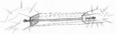
Figure 5. In Step 3, the convex hull of two polygons (shaded)
gives a "prismatoid" (dotted) around each segment.
Step 2. Make Polygons around
Endpoints. In order to form these segment-surrounding
polygons, we construct a simple convex polyhedron around each endpoint in such
a way that its vertices lie between the outgoing segments. This is simply
the dual to the convex hull of the points where the segments intersect a small
sphere. For example, if six orthogonal segments meet at a given endpoint
(Fig 6a) they define the six vertices of a small octahedron surrounding that
point (Fig 6b). The dual to the octahedron is a cube (Fig. 6c) which has
six square faces, one surrounding each segment.
Notice that this dual
polyhedron can be scaled for thicker or thinner struts, within certain
limits. This is called the scale factor parameter, and can be
different for each vertex.
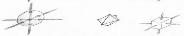
Figure 6. In Step 2, a) construct points around a vertex where
segments meet small sphere, (b) form their convex hull, and (c) construct dual
polyhedron.
Step 1. Ensure Endpoints are
Enveloped. The step 2 procedure would fail if there were
not enough points to define a polyhedron. So if there are fewer than four
segments at a vertex, we first add "pseudo segments" to make a
tetrahedral arrangement. Even with more than four, the arrangement may
fail to form a polyhedron that surrounds the given endpoint, e.g., if the segments
all lie in a plane or half-space. There is a short list of troublesome
configurations to search for, illustrated in Fig. 7.
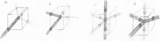
Figure 7. In Step 1, if the real segments (dark) do not produce an
arrangement which surrounds the vertex, add "pseudo segments" (light)
which do.
The following list of cases,
in this sequence, seems to be sufficient: (other methods could be employed)
a) If there is only one segment, add three more as a regular
tetrahedron.
b) If there are two segments not opposed, add two more as a tetrahedron.
c) If there are two opposed segments, add three on their "equator" as
a triangular dipyramid.
d) If all the segments lie in a plane, add two "poles" orthogonal to
the plane.
e) If all the segments lie in a half-space, add one in the direction opposite
their mean.
Cases
(d) and (e) are not exclusive; consider a small fan of segments. The nature of
duality guarantees that every face of the dual surrounds either a segment or a
pseudo-segment. The faces which surround the real segments are used as the
bases of the prismatoids. They are not output as part of the
result. Only the sides of the prismatoids and the faces which surround
pseudo-segments are output.
All the above operations are
straightforwardly implemented with standard vector operations. A suitable 3D
convex hull subroutine is required, but this is a well-studied problem and many
implementations exist.
5. Examples
For
experimental purposes, the algorithm has been implemented in Mathematica
using floating-point values. When efficiently implemented, the computational
complexity of the entire process will be that of the many small convex hull
operations, one about each vertex and one about each segment. The results
are attractive and lucid, producing well-designed facets, with a low number of
polygons. It is found to function well even in complex structures with
several thousand segments to enclose. Three finished pieces and a new
design are discussed below.
5.1 Deep Structure.
 Shown in Figure 1 above,
there are 720 struts in each of the five layers plus 480 struts which connect
adjacent layers. The 4080 segments are wrapped with 27214 triangles altogether,
which bound the struts. The close-up image in Figure 8 shows some of the
diagonal inter-layer struts, and makes clear the slight degree of randomness
introduced because they start at a random phase in each oval.
Shown in Figure 1 above,
there are 720 struts in each of the five layers plus 480 struts which connect
adjacent layers. The 4080 segments are wrapped with 27214 triangles altogether,
which bound the struts. The close-up image in Figure 8 shows some of the
diagonal inter-layer struts, and makes clear the slight degree of randomness
introduced because they start at a random phase in each oval.
Figure 8. Close up view of Figure 1 shows texture and
layering.
For the structure of each
layer, I chose the edges of a 31- zone zonohedron, illustrated in Figure 9,
which has edges in the 31 directions of the icosahedron's axes of symmetry. It
is a 242-sided polyhedron bounded by thirty 12-gons, twelve 10-gons, eighty
6-gons, and one hundred twenty squares. [11] It is particularly easy to build a
physical model of this polyhedron with the Zometool modeling set. [14]
Figure 9 is generated by a program I wrote which presents polyhedra in the
solid-segment style of Leonardo da Vinci, discussed above, which helps to make
clear the elegant structural aspects of this polyhedron. Although it is
straightforward to make a 3D printing of the form in Figure 9, I would consider
that a mathematical model, not a sculpture. Comparing it to Figures 1 and
8 should make clear the type of sculpted, chiseled look I was after.
Figure 9. 31-zone zonohedron that underlies each layer of Figs 1 and 8.
5.2 Five-Legged-Bee Hive.
 Shown in Figure 2 above, this sculpture is based on the 120-cell. The
underlying 4-dimensional structure consists of 120 regular dodecahedra,
arranged so three meet around each edge and four meet at each vertex.
Shown in Figure 2 above, this sculpture is based on the 120-cell. The
underlying 4-dimensional structure consists of 120 regular dodecahedra,
arranged so three meet around each edge and four meet at each vertex.
In 3D, regular dodecahedra
do not pack like this without gaps, but in 4D there is freedom to rotate them
slightly to pack snugly. A shadow of the 4D edge arrangement onto 3D space
gives the mathematical form underlying this sculpture. If the edges were
straightforwardly rendered by the above algorithm, the structure in Figure 10
could result, but for 3D printing the struts would probably be made
thicker. However, as a sculptor, I am interested in modifications which
produce visually interesting effects, so I made a small variation to the
algorithm, by which the faces corresponding to pseudo-struts are placed further
from their vertex than other faces. This is actually accomplished by
making the pseudo-strut points closer to the vertex before taking the dual in
step 2 above. Doing so produces the sculptural form of Figure 2 rather than the
mathematical model in Figure 10.
Figure 10. Edges of 120-cell orthogonally projected from 4D to 3D, along the
direction to the center of a cell
5.3 120-cell projected as
"Schlegel Diagram"
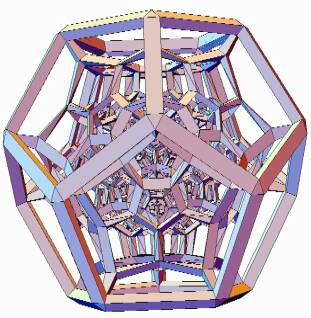
Figure 11.
120-Cell projected in perspective, like Schlegel Diagram
Figure 11 shows the design
for a perspective projection of the 120-cell into 3D space, taken from very close
up in 4D space. The effect is analogous to a 2D "Schlegel
diagram" [3] of a 3D polyhedron. There are 119 dodecahedral cells
packed inside the 120th outer cell. In general, elegant effects can
result if the strut scale factor varies as a function (either increrasing or
decreasing) of the distance of a vertex from the polytope center. In this
case, the small inner cells are made with a strut thickness proportional to
their smaller distance from the center. This design was worked out in discussions
with Carlo Sequin. The 3D printing in Figure 12 is 5 cm across, executed
and photographed by Bathsheba Grossman [4] with a Sanders prototype machine
[17].
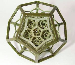
Figure 12. Wax realization of Figure 11, 5 cm diameter
5.4 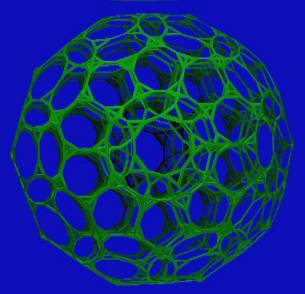 Truncated 120-cell.
An as-yet-unrealized form is analogous to Figure 10, but
truncated (in 4D) at each vertex. This is a cell-first orthogonal
projection of the "truncated 120-cell," a 4D polytope consisting of
120 truncated dodecahedra and 600 regular tetrahedra, first described in a 1910
paper written by Alicia Boole Stott (a daughter of George Boole) [3, 15].
In this projection it produces a stunningly beautiful 3D form with 10-sided
passageways piercing it in six different directions A large and
very rewarding physical model can be made using Zometools; instructions are
given in [14].
Figure 13. Projection of edges of truncated 120-cell
6. Conclusions
A
simple, efficient algorithm has been presented which can be applied to problems
in 3D design where segments need to be rendered as struts. Its use as a
tool in sculpture and the design of mathematical models has been
demonstrated. Beautiful forms have been constructed by this means,
including several examples of sculpture and models which I hope to
realize soon. For additional information about my sculpture, see my web
pages at [5].
References
[1]
John Boylan, "Ugworm," in Carlo Sequin, Procedural Generation of
Geometric Objects, U.C. Berkeley Comp. Sci Division Report #UCB/CSD89/518,
June 1989
[2] Marshall Burns, Automated
Fabrication: Improving Productivity in Manufacturing, Prentice Hall, 1993.
[3] H.S.M. Coxeter, Regular
Polytopes, Dover reprint, 1963.
[4] Bathsheba Grossman, http://www.protoshape.com/
[5] G.W. Hart, Geometric
Sculpture, http://www.georgehart.com/
[6] G.W. Hart,
"Sculpture based on Propellorized Polyhedra," Proceedings of MOSAIC
2000, Seattle, August, 2000.
[7] G.W. Hart, "The
Millennium Bookball," Proceedings of Bridges 2000: Mathematical
Connections in Art, Music and Science, Southwestern College, Winfield,
Kansas, July 28-30, 2000.
[8] G.W. Hart,
"Reticulated Geodesic Constructions," Computers and Graphics,
to appear 2000.
[9] G.W. Hart,
"Loopy," to appear in Humanistic Mathematics.
[10] G.W. Hart,
"Icosahedral Constructions," in Proceedings of Bridges:
Mathematical Connections in Art, Music and Science, Southwestern College,
Winfield, Kansas, July 28-30, 1998, pp. 195-202.
[11] G.W. Hart,
"Zonohedrification," The Mathematica Journal, vol. 7 no. 3,
1999.
[12] G.W. Hart, "Zonish
Polyhedra," Proceedings of Mathematics and Design '98, San
Sebastian, Spain, June 1-4, 1998.
[13] G.W. Hart, "Calculating
Canonical Polyhedra," Mathematica in Research and Education, Vol. 6
No. 3, Summer, 1997, pp. 5-10.
[14] G.W. Hart and Henri
Picciotto, Zome Geometry: Hands-on Learning with
Zome Models, Key Curriculum Press,
2001.
[15] Alicia Boole Stott,
"Geometrical deduction of semiregular from regular polytopes and space
fillings," Verhandelingen der Koninklijke Akademie van Wetenschappen te
Amsterdam, (eerste sectie), Vol. 11, No. 1, pp. 1-24 plus 3 plates, 1910.
[16] Zcorp, http://www.zcorp.com/
[17] Sanders, http://www.sanders-prototype.com/